How to Make a 3D Model | CAD Basics for Beginners
The first thing I ever modeled was a tiny spacer for a desk leg. It was off by just 0.5 mm and wouldn't fit — but when I corrected the dimension in CAD and re-exported it immediately, I realized 3D modeling isn't about drawing pretty pictures. It's about designing solutions.
This article is for beginners who want to start modeling for 3D printing. We'll sort out which method and software to pick based on what you actually want to make. Practical objects call for a CAD tool like Fusion 360, freeform shapes work best in Blender, and if you're an absolute beginner, Tinkercad is the fastest way in.
We'll also walk through the full workflow — from design to STL/3MF export, slicing, and printing — along with five concrete steps to finish your very first project. By the time you've covered the pre-print checks (watertight geometry, normals, thin walls, mm-scale verification) and the 4-week and 3-month learning roadmaps, you'll be able to design, print, and iterate without spinning your wheels.
What Is 3D Model Creation? Start by Deciding What to Make
3D model creation means building three-dimensional geometry in software. Unlike 2D drawings and illustrations, 3D involves width, depth, and height. If you're getting into this for 3D printing, think of it less as "making something look good on screen" and more as "defining an object at a specific size." That mental shift keeps your learning on track.
Most beginners stumble not because the software is hard but because they start without a clear idea of what they're making. Pick a small object with a clear use case — a cable clip, a desk-leg spacer, a drawer divider, a figure stand. When you know how the finished piece will be used, design decisions start making sense. Personally, whenever I'm modeling something practical, I lock in the finished dimensions before I open any software. Once height, width, and depth are set, the features and tolerances I need become obvious.
3D Space Fundamentals
Position and size in 3D space are expressed along three axes: X, Y, and Z. Typically X is left-right, Y is front-back, and Z is up-down. A 2D drawing lives on the X-Y plane; a 3D model adds Z, which is what lets you distinguish a flat plate from a box from a column.
This matters a lot for 3D printing. A shape that looks correct from above might be too short to serve its purpose, or too tall to clear surrounding objects. CAD software suits practical parts so well because dimensions are stored as numbers and can be changed later without breaking the rest of the geometry. Autodesk's parametric modeling overview explains how shapes are defined through values and constraints, and even for small 3D-printed objects, that approach pays off heavily.
From my own experience, the first print you ever make succeeds or fails on size accuracy, not appearance. A cable clip needs the right cable diameter and mounting width. A desk-leg spacer needs the correct inner dimension and wall thickness. A figure stand needs to match the base of whatever you're displaying. Starting from what the part must hold, and at what size, gives your modeling a clear purpose.
The Role of Three-View Drawings
A simple way to stay oriented while designing is to think in three views: front, side, and top. You don't need formal drafting — a quick hand sketch is enough. For practical objects, even a rough three-view sketch dramatically reduces design oversights.
Say you're building a drawer divider. The front view pins down height and wall thickness, the top view lays out the compartments, and the side view confirms depth. I once built a drawer divider while focusing only on the top-down layout and forgot to note the Z-axis height. The divider went in fine, but the drawer lid wouldn't close. Since then, I always jot down the height on my sketches, no matter how simple the part seems. In 3D printing, a shape can look perfect from above and still fail because the Z dimension is wrong.
What makes three-view sketches so useful is that they force you to articulate design requirements before you touch any software. For a cable clip: the top view shows the cable path, the side view shows the clip opening, and the front view captures the thickness. For a figure stand: the top view defines the platform shape, the side view sets the height, and the front view reveals the edge profile. Especially for beginners, sketching on paper before jumping into extrusions and revolves helps you hold onto the end goal.
💡 Tip
Even for parts that seem too simple to sketch, spending one minute on front/side/top notes cuts down on mid-modeling hesitation. The more practical the part, the bigger the payoff.
A helpful illustration here would show the X/Y/Z coordinate axes alongside the three standard views. Many people who struggle with 3D navigation find that paper sketches suddenly make everything click.
The Full 3D Printing Workflow
Creating data for 3D printing doesn't end at modeling. The basic flow is 3D model creation, export to STL or 3MF, slicing, then printing. Knowing this sequence up front prevents the classic confusion of "I made the shape but it won't print."
After modeling, most workflows involve exporting as STL or 3MF. STL is the long-standing standard — it stores geometry as a collection of triangles. However, it carries no unit or color information, which limits what downstream tools can work with. 3MF retains units, colors, and material data, making it easier to pass richer information to the next stage. Whether you're in Fusion 360 or Blender, there's always this "hand off to a print-ready format" step. Fusion 360's 3D print export is accessible through a dedicated menu (covered in Autodesk tutorials), and Blender, as Uno Laboratory's guides explain, handles the modeling portion before handing off to a slicer.
In the slicing stage, the model is converted into layer-by-layer instructions the printer can execute. Orientation, supports, and layer settings are determined here, producing the actual print file. Modeling, in other words, is a prerequisite — not the finish line. Beginners benefit from writing out this sequence on paper. Adding software names makes it even clearer: "Build the shape in Fusion 360," "Export as STL or 3MF," "Import into the slicer," "Print." Just that list shows you where each tool fits.
A diagram linking model creation, export, slicing, and printing with arrows conveys the whole pipeline at a glance. Once you see this flow before starting, choosing a good first project becomes easier. Simple shapes like cable clips or drawer dividers are ideal first projects precisely because they let you practice the entire chain while keeping complexity low.
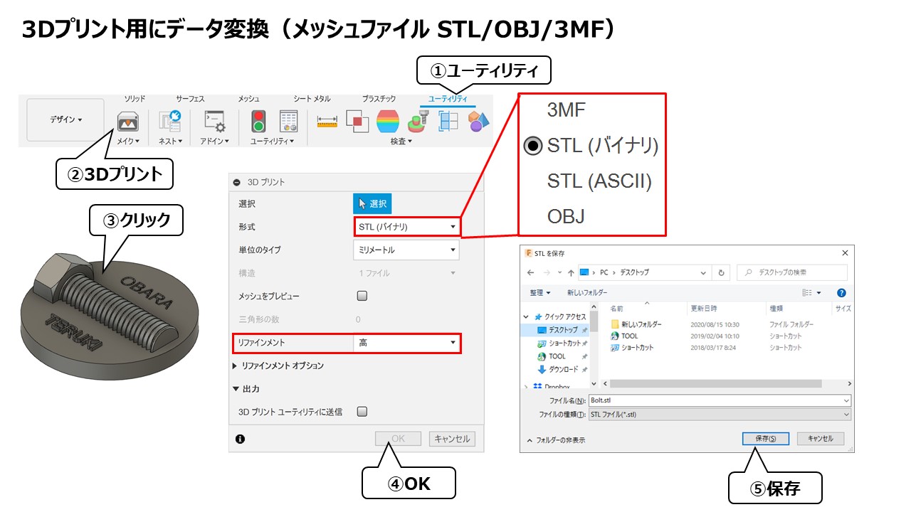
3Dプリント(3Dプリンタ用のデータ出力【3MF/STL/OBJ】について)
Fusion360で作成したモデルを3Dプリンタ用のファイル形式に出力する場合は、ツールメニューから「ユーティリティ」→「3Dプリント」というボタンをクリックするか、「ファイル」→「3Dプリント」からも実行できます。「3Dプリント」を実行後
fusion360.teruemon.comThree Approaches to 3D Modeling | Polygon vs. Sculpt vs. CAD
Broadly speaking, there are three methods: polygon modeling, sculpt modeling, and CAD modeling. All three produce 3D geometry, but they think about shape very differently. If you pick software without understanding these distinctions, you're likely to feel stuck before you even start learning controls.
From a 3D printing perspective: CAD is strongest for functional parts and mechanical components, while sculpting and Blender-style modeling excel at organic forms like figures and characters. Polygon modeling sits in between — high in creative freedom and well suited for detail-oriented visual work. I switch between methods depending on the project, and even the same object can feel completely different to build depending on which approach I use.
A while back, I tried prototyping a cable clip using polygon modeling in Blender. The shape came together, but once I started dialing in wall thickness and edge radii, making precise changes without breaking the visual form took much longer than expected. I switched to CAD, rebuilt it with dimension-driven design, and edits became dramatically faster. For functional 3D-printed parts, CAD's advantage was unmistakable.
A useful diagram here would plot the three methods on two axes — functional vs. artistic and precision vs. freedom — to give an intuitive sense of where each method sits.
| Method | Strengths | 3D Print Suitability | Difficulty | Key Software |
|---|---|---|---|---|
| Polygon | Props, product shells, game/CG models, freeform shapes | Good for visual objects and appearance-focused prints | Medium | Blender |
| Sculpt | Figures, characters, animals, sculptural objects | Strong for organic shape output | Medium–High | Blender, ZBrush |
| CAD (Solid/Parametric) | Functional parts, jigs, enclosures, mechanical components, dimension-critical models | Ideal for practical and mechanical prints | Medium | Fusion 360, Tinkercad |
Polygon Modeling Basics
Polygon modeling builds shapes from collections of faces. You place a box, extrude faces, add edge loops, and gradually refine the form. It's the foundational 3D modeling technique, widely used in CG, animation, and game asset creation, with Blender as the go-to tool.
Beginners often find it approachable because the shape is understood as an "assembly of faces" rather than digital clay. A phone stand or a simple enclosure, for example, can start from a cube or cylinder and evolve through straightforward edits. The structure of the geometry stays visible, which helps build spatial understanding. Because you're shaping the appearance directly, this method appeals to anyone who wants visual control.
That said, when precision matters — hole diameters, wall thickness, fillet radii — polygon modeling can feel like a detour. You absolutely can build functional parts this way, but repeated dimensional tweaks are where CAD pulls ahead. Uno Laboratory's Blender-for-3D-printing guide frames Blender as the modeling stage that then feeds into print-ready export, which is a practical way to think about it.
Polygon modeling fits people who want creative freedom without going full sculpt. It works well for artistic props, appearance-driven enclosures, and base meshes for figures, and pairs naturally with a Blender-centered learning path.
【2026】Blenderで3Dプリンター用データを作る方法の注意点は?【フィギュアにも】
今回は、Blenderを使って3Dプリンター用の3Dデータを作る方法について初心者向けに解説します。Blenderを使って3Dプリンターで出力したことがないという方が、3Dプリンター用のデータ作成ならではの手順と注意点について理解できるよう
unolaboratory.comWhat Makes Sculpt Modeling Different
Sculpt modeling shapes geometry the way you'd shape clay — pushing, pulling, adding, and carving. Instead of building face by face, you work with a mass, deforming it with brush-like tools. The feel is closer to physical sculpture, and it excels at wrinkles, muscles, fabric drape, and other organic detail.
For 3D printing, sculpting shines with figures, creatures, animals, busts, and decorative elements — anything where the "expression of the form" matters more than exact measurements. Flowing hair, fabric folds, and facial features are far more natural to create in sculpt mode than in CAD. Blender includes sculpt tools alongside its polygon toolset, so you can switch between the two workflows seamlessly.
The trade-off is dimensional control. Sculpting is intuitive for shaping, but snapping to exact measurements or maintaining mechanical symmetry isn't its forte. If you need parts that mate precisely, or enclosures that must fit within tight tolerances, CAD is a better starting point. When sculpting for 3D printing, plan on a finishing step to ensure the mesh is export-ready.
💡 Tip
Subjects that call for natural curves — figures, animals, organic ornaments — are where sculpting saves time. For anything driven by specific measurements, starting in CAD will keep you from second-guessing your approach.
Sculpting is the method that rewards artistic instinct most directly. It's the closest digital equivalent to working with your hands, and for anyone drawn to expressive form-making, it's deeply satisfying. In a 3D printing context, think of it as oriented toward art and creative objects rather than functional parts.
The Strength of CAD (Solid/Parametric)
CAD builds shapes through dimensions and precision. It's the backbone of manufacturing, architecture, and industrial design, and it's exceptionally well suited to functional 3D-printed parts. The workflow — sketch a profile, extrude it, cut holes, add fillets and chamfers — constructs geometry that's defined by numbers.
The standout feature is parametric modeling. As Autodesk's parametric modeling page explains, shapes are defined by values and constraints, which means changing a dimension later doesn't require a redesign. Widening a cable clip, thickening a case wall, shifting a hole — these edits are fast, and that speed aligns perfectly with the prototype-print-revise cycle of 3D printing.
This method is unambiguously the best choice for functional and mechanical parts. Jigs, spacers, hooks, brackets, storage trays, device mounts — whenever "it has to work" outweighs "it has to look interesting," dimensional flexibility is what matters. In my own workflow, any time I need a part to fit precisely or I know I'll iterate on dimensions, I reach for Fusion 360.
Among CAD tools, Tinkercad is the easiest on-ramp, and Fusion 360 is the natural next step. Tinkercad is a free, browser-based tool from Autodesk where you combine primitives and export to STL, OBJ, and other formats. Fusion 360 is more design-oriented, with strong 3D printing integration; Autodesk offers a 30-day free trial on their official page. Personal-use free tiers and paid licensing exist, but the key takeaway at this stage is: if you want to build practical objects, getting comfortable with CAD thinking early saves you time later.
When you're torn between the three methods, let the object decide. Clips, hooks, and fitted enclosures point to CAD. Characters, animals, and decorative pieces point to sculpting or Blender. Appearance-focused objects that still need structured faces point to polygon modeling. For 3D printing, understanding this method-level distinction matters more than memorizing software names.
CAD Fundamentals for Beginners | Core Operations and Mindset
The Heart of Parametric Thinking
The single most important concept when you first open a CAD tool is this: you don't sculpt the shape directly — you define it with numbers and rules. That's the essence of parametric modeling. Geometry is controlled through values like width, height, thickness, and hole position, combined with constraints that lock relationships between features. As Autodesk's parametric modeling guide outlines, the payoff is resilience to design changes.
Imagine you're building a small enclosure and you realize the width needs to grow slightly, or only the interior cavity needs more room. With parametric CAD, you don't start over. You edit the sketch dimension, and the extruded body — along with every hole, fillet, and chamfer you added afterward — updates through the feature history. I once needed to widen an enclosure's interior by just 0.3 mm during prototyping. I opened the original sketch, changed one number, and the entire model updated. Moments like that drive home that CAD isn't a drawing tool — it's an engineering tool built for change.
Once this mindset clicks, the learning path becomes clear. The first skills to build aren't flashy features but the fundamentals: set a reference, define dimensions, and grow the shape from there. Visual polish comes later. Early on, focus on "where is my reference?" and "which values am I locking down?" That discipline produces models that survive revision after revision.
The Minimum Set of Operations and Terms
The vocabulary you need at the start is small. Mastering a few operations deeply beats skimming many. The essentials are sketch, dimensions and constraints, extrude, fillet, chamfer, and hole. Once those feel natural, add pattern and mirror, and you'll be equipped to model a surprisingly wide range of functional parts.
A sketch is the 2D foundation of any 3D feature. You draw circles, rectangles, and lines, then assign dimensions. Nailing widths and positions at this stage means the 3D result is stable. Dimensions aren't just lengths — they encode intent: "this hole sits 10 mm from center," "this fillet radius is 2 mm." Constraints lock geometric relationships: keeping lines horizontal or vertical, aligning centers, enforcing symmetry. Think of constraints as rules for how the shape behaves.
Extrude takes that 2D sketch and gives it depth to become a 3D solid. A rectangle becomes a box; a circle becomes a cylinder. For small 3D-printed parts, the sketch-then-extrude sequence alone is enough to rough out a huge number of designs.
Fillet rounds edges; chamfer bevels them. Beginners often see these as cosmetic, but on functional parts, a fillet softens a grip surface or eases insertion, while a chamfer guides alignment. The hole tool does exactly what it sounds like — cuts through-holes, counterbores, or pilot holes for screws. Pattern repeats a feature at equal intervals; mirror duplicates it symmetrically. Lining up screw holes or creating a symmetric hook shape becomes almost instant with these two.
Design-wise, start every sketch from a reference plane — front, top, or side. Deciding which plane to begin on eliminates a surprising amount of confusion. This mirrors the three-view sketch concept (front, side, top) and makes models easier to read. Also, build symmetry around the origin whenever possible. If you sketch symmetrically about a centerline, changing the width later preserves balance automatically.
💡 Tip
A great first exercise: sketch a rectangle, extrude it into a box, fillet the edges, and cut a hole in the top face. It covers the core CAD operations end to end and directly applies to real 3D-printed parts.
A step-by-step diagram showing the shape evolving through sketch, extrude, fillet, hole makes this tangible. The finished form can look intimidating, but broken into stages it's just "drew a rectangle," "gave it depth," "rounded the edges," "punched a hole." Something that's often overlooked: CAD fluency comes less from memorizing commands and more from repeating this basic sequence until it's second nature.
Common Beginner Mistakes and How to Avoid Them
The most frequent stumbling blocks aren't about specific buttons — they're about thinking in the wrong order. A typical pattern: jumping straight into complex geometry without establishing a reference, stacking features without constraints, and then discovering that changing a single width cascades into unpredictable edits.
The fix is straightforward — decide what your reference is before you draw anything. If the part is centered, place it on the origin. If it's symmetric, draw a centerline. If a wall thickness is constant, lock that into the first sketch. Just following this sequence dramatically stabilizes your model. For 3D-printed enclosures and jigs especially, design from the inside out: start with the dimensions of whatever goes inside, then add wall thickness around it.
Another common issue is sketching without adding dimensions or constraints. A rectangle might look right, but without numerical definition it can drift when you edit something else. In CAD, "I drew it" matters less than "I defined it." Asking yourself which widths, heights, center positions, and symmetry relationships are needed produces data that holds up under revision.
Applying fillets and chamfers too early is a subtler trap. Edge treatments are useful, but adding them before the core geometry is stable can make the feature history harder to follow when you need changes later. Build the box, the plate, the cylinder first. Lock in hole positions and overall dimensions. Then round and bevel. Treating cosmetic operations as a finishing pass rather than a building-block step prevents a lot of mid-project confusion.
From hands-on experience, beginners tend to aim for "drawing well" when the real target in CAD is "defining well." Even a plain box with a single hole, if it's sketched from a reference plane, built symmetrically about the origin, and dimensioned properly, becomes trivially easy to resize later. That unsexy workflow is exactly what pays off most when you're modeling functional parts for 3D printing.
Hands-On: 5 Steps to Model a Simple Object
This workflow is easiest to follow in a parametric CAD tool like Fusion 360. The example project is a cable clip — its circular cross-section makes it easy to break down, and it's a natural candidate for dimension-change practice. The sequence: decide what to make, measure, 2D sketch, extrude into 3D, add edge treatments and holes, then export as STL/3MF.
- Decide what to make and write down the target dimensions
- Measure the real-world object
- Create a 2D sketch
- Extrude into a solid
- Add edge treatments and holes, then export to STL or 3MF
Step 1: Purpose and Target Dimensions
First, nail down what the part needs to hold. For a cable clip, the shape differs depending on whether you're securing a USB cable to a desk edge or bundling charging cables against a wall. Starting without that clarity means you'll keep adding and removing dimensions mid-build.
What you jot down on paper isn't a polished drawing. You need four things: overall width, thickness, height, and where the cable sits. A top view showing the outline, a side view capturing the thickness, and the cable path location — that's enough. The three-view system uses front, side, and top, but for small beginner parts, even top and side alone cut decision fatigue significantly.
At this stage, getting the target dimensions onto paper before opening CAD is what matters. If you start thinking about dimensions inside the software, the interface competes for your attention and design intent gets fuzzy. Whenever I'm making something small, I write down "what it holds" and "how far it can stick out," then open Fusion 360. That habit keeps later revisions grounded.
Step 2: Measuring Tips
Next, measure the real object. For a cable clip, the key numbers are cable outer diameter, the opening width for insertion, and overall clip thickness. Calipers are the right tool here — use outer diameter for round objects, inner diameter for openings and slots, and thickness for flat sections.
One important lesson: the measured value isn't always the value you use in CAD. When I made a clip for a 4 mm-diameter cable, the first version was noticeably tight. It looked fine on screen, but inserting the cable required real force and removing it was a hassle. On the second print, I added a small amount of clearance and it worked perfectly. Tolerances vary with your printer and layer settings, so treat the first print as a test piece.
Record measurements with labels — "cable OD," "opening width," "body thickness" — rather than bare numbers. Labeled notes are far easier to transfer into a sketch and far more useful when you revisit the design weeks later.
Step 3: Sketching
With measurements in hand, open Fusion 360 and start a 2D sketch. Drawing the top-down outline is usually the clearest approach. Set a centerline near the origin, then build the profile symmetrically. For a cable clip, placing the arc or U-shape symmetrically about the centerline means width changes won't throw off the balance.
In this step, prioritize constraints and dimensions over visual appearance. Lock lines to horizontal and vertical, apply symmetry, and assign the width and opening dimensions from your measurements. Defining the shape from the origin rather than free-drawing and adjusting later makes future edits smoother. Autodesk's parametric modeling overview covers this philosophy in detail, and for beginner-level functional parts, the "control shape with numbers" mindset is exactly what you need.
For a cable clip, keep the sketch straightforward — the outer profile is a combination of rectangles and arcs. Lay out the body outline first, then the cable groove, and optionally the mounting-hole locations. Sorting everything in 2D before thinking in 3D makes the extrude step far simpler.
Step 4: Extrude and Wall Thickness
Once the sketch is done, extrude it into a solid. Think about the body height and which areas to cut away as separate operations. For example, extrude the full outline into a slab, then cut the cable groove and any slots. Resist the urge to do everything in one feature — separating the base shape from functional cuts keeps the feature history readable.
Pay attention to wall thickness at this stage. Too thin and the part feels flimsy; too thick and it looks bulky. On a cable clip, keep the cable-gripping section from getting too narrow while giving the body enough meat to feel solid. Consistent wall thickness alone goes a long way toward making a print look finished.
I usually check at this stage whether the extruded shape works as a simple slab or block. A clean skeleton makes the subsequent edge treatments look intentional. If the base geometry is vague and you start adding decorative rounds, you end up with more work when revisions come.
Step 5: Edges, Holes, and Export
With the solid in place, finish with edge treatments and holes. Fillet the edges where fingers will touch or where the cable enters and exits — this softens the feel and improves usability. Chamfers can help with insertion alignment. For holes, decide whether they're through-holes for mounting or pilot holes for screws. You can model a pilot hole and tap the thread post-print if needed.
To export from Fusion 360, go to Utilities > 3D Print (or File > 3D Print depending on your version). For 3D printing handoff, STL is the baseline format. It's universally supported by slicers but carries no unit information, so watch for scale mismatches on import. 3MF retains units, color, and material data, making it a cleaner handoff when your workflow supports it. A sensible progression: start with STL, then adopt 3MF once you're comfortable with the pipeline.
Autodesk's tutorials on exporting Fusion 360 models for 3D printing show exact menu locations. For simple parts the file stays small, but highly curved surfaces with fine tessellation can balloon the triangle count. Getting into the habit of checking whether the mesh is finer than it needs to be helps keep slicer performance stable.
💡 Tip
Two diagrams work well here: a 5-step progression showing "paper sketch, measure, CAD sketch, extrude, edge treatment," and a screenshot frame highlighting the export menu location in Fusion 360.
Choosing Software | Is Tinkercad, Fusion 360, or Blender Right for You?
Picking a 3D modeling tool for printing is less about feature count and more about what you plan to build. Fitted enclosures, jigs, and hooks — anything driven by dimensions — favor Fusion 360. Characters, figures, and organic forms suit Blender. Tinkercad sits a step before both, offering the fastest possible path from zero to a tangible shape in the browser.
From a 3D printing standpoint, the differences are sharp. Fusion 360 lets you "enter a number and change it later," which is exactly what functional parts need. Blender gives you high visual fidelity and surface control for sculpted detail. Tinkercad lets you combine cubes and cylinders with boolean operations, making the concept of additive and subtractive modeling immediate and accessible.
I started with Tinkercad myself, learning how combining and subtracting primitives works. Once the "add shape, cut shape" logic clicked, I moved to Fusion 360 over a weekend. The biggest difference I noticed was dimensional stability — being able to store widths and hole diameters as editable values cut down on post-print redo cycles dramatically. It's not glamorous, but for functional parts, that's where the real gains are.
The Quick Answer
If you need a single-sentence recommendation: Fusion 360 for functional parts, Blender for creative forms, Tinkercad for kids and absolute beginners.
Phone stands, cable clips, enclosures, spacers — anything where "widen by 1 mm" or "shift this hole" happens regularly — belong in Fusion 360. Parametric design makes iteration fast. Figures, mascots, creatures, ornamental objects — anything where cheekbone curves or fabric folds matter more than millimeter precision — belong in Blender. Freeform sculpting and polygon editing handle that kind of detail naturally.
Tinkercad is the right starting point for anyone touching 3D-printable data for the first time. It's browser-based, requires no installation, and is completely free. Use it to experience the full loop: place a shape, cut a hole, export STL. It's often associated with classroom use, but it works just as well for adults getting oriented.
Fusion 360 is more design-focused, with strong 3D printing integration. Autodesk's official page offers a 30-day free trial. Personal-use free tier eligibility (revenue caps, usage restrictions, etc.) can change, so always verify current terms on Autodesk's official licensing FAQ. Regardless of licensing details, the core point holds: picking up CAD thinking early pays dividends if functional parts are your goal.
Here's a print-oriented comparison:
| Software | Strengths | Cost | Learning Curve | 3D Print Fit | Best For |
|---|---|---|---|---|---|
| Tinkercad | Absolute beginner entry, simple objects, jigs, box prototypes | Free | Low | Understanding shapes and first exports | Kids, complete beginners, "just want to print one thing" |
| Fusion 360 | Enclosures, jigs, hooks, spacers, dimension-driven functional parts | Personal free tier available (check official terms for eligibility) | Medium | Strong for precision-dependent prints | People building practical parts, iterative prototypers |
Note: Some third-party sources cite an annual price around 61,600 yen (~$410 USD) for Fusion 360, but actual pricing varies by region, currency, and tax treatment. Always refer to Autodesk's official purchase page for current pricing.
| Blender | Figures, characters, props, freeform surfaces | Free | Medium–High | Powerful for creative forms; may require mesh cleanup | Detail-oriented creators, visual-first modelers |
A decision-tree diagram works well here: "What are you making?" branches to enclosure/jig (Fusion 360), figure/organic (Blender), or "just want to try" (Tinkercad).
Strengths and Weaknesses of Each
Tinkercad's strength is immediacy — you can produce shapes without any instruction. Stacking boxes, cylinders, and cutouts is enough to make name tags, simple stands, and quick spacers. It exports to STL, OBJ, GLTF, SVG, and more, so it covers the basics well. The limitation is that it doesn't support history-based parametric editing. Once prototyping progresses to "change just this width" or "reorganize hole positions after the fact," you'll hit the ceiling.
Fusion 360's strength is reliability for parts you actually use. The sketch-constrain-dimension-extrude flow is explicit, and changes propagate through the feature tree, which matches the print-test-revise cycle perfectly. Snap-fit parts and storage cases — anything where half a millimeter shifts the user experience — are where it excels. The learning curve is real: you need to think about references and constraints rather than free-drawing. But for anyone with a clear functional goal, that structure actually makes learning easier.
Blender's strength is expressive power. Polygon and sculpt tools let you push surface detail as far as you want, making it the tool of choice for figures, ornaments, and anything with organic character. For 3D printing, it handles wrinkles, flowing hair, and textured surfaces that CAD simply can't produce. The weakness, from a functional-part perspective, is that precise dimensioning is cumbersome. Complex meshes also tend to accumulate normals issues, non-manifold geometry, and other artifacts that require cleanup before export.
Viewed through a 3D printing lens, Fusion 360's weapon is "ease of redesign" and Blender's weapon is "expressive range." Tinkercad is the gateway you pass through before committing to either direction. These aren't competing on the same axis — they embody different design philosophies.
💡 Tip
My personal recommendation: learn additive/subtractive logic in Tinkercad, then move to Fusion 360 when you're ready for functional parts. The only exception is if you specifically want to make figures — in that case, head to Blender sooner rather than later.
Price Context for Professional CAD
Discussing Fusion 360 and Blender can give the impression that all CAD software is expensive. The reality is that the price range is enormous — from free to industrial-grade investment. Understanding where Fusion 360 sits helps frame its value.
A useful reference point is ZW3D 2026. ZWSOFT's official blog offers a 30-day trial, with perpetual license pricing at 313,000 yen (~$2,100 USD) for Lite, 604,000 yen (~$4,000 USD) for Standard, and 1,683,000 yen (~$11,200 USD) for Premium. Against that backdrop, Fusion 360's personal free tier and Blender's zero cost make both remarkably accessible entry points.
The takeaway: at the hobby and small-scale prototyping stage, you don't need expensive software to do serious work. Fusion 360 brings real design capability at a low barrier to entry, Blender removes cost as a factor entirely, and Tinkercad lets you confirm whether 3D modeling clicks for you before committing to anything. Choose based on what you're making and how much revision resilience you need, not on price alone.
Pre-Print Checklist | What to Verify Before Exporting STL
Essential Check Items
A model that looks complete on screen may not be ready for the printer. STL in particular — because it represents shapes as collections of triangles — is prone to picking up holes, missing faces, and flipped normals during conversion. Something that renders fine in the viewport can open in the slicer with missing sections or an interior that isn't recognized as hollow. A fixed checklist before export is the most reliable way to prevent "it looked right but won't print."
The first thing I check is whether the model is watertight — meaning it forms a fully enclosed volume with no gaps. A single missing face or edge hole, even if it's tiny on screen, can cause major print failures. Along the same lines, watch for non-manifold edges: places where faces meet an edge in geometrically invalid ways, or paper-thin sections with no volume. Slicers can't interpret these as solid geometry, and the result is unpredictable.
Normal orientation matters too. Every triangle in an STL has a normal vector that determines which side is "outside." I once exported a model without noticing some normals were flipped, and the printer laid down filament in mid-air over that section. On screen the mesh looked closed, but the slicer interpreted part of it as inside-out. Since then I always visualize normals and confirm they all point outward. This one step saves an outsized amount of trouble, especially in Blender-based workflows with freeform geometry.
Wall thickness is another pass/fail factor. Walls that are too thin either vanish during slicing or print so fragile they break immediately. Decorative ribs, embossed text, and thin fins are the usual culprits — they look reasonable in CAD but can't be reproduced at print scale. Even when CAD shows a valid thickness, STL conversion can pinch certain areas thinner than intended, so verify with a thickness analysis or cross-section view rather than trusting the viewport.
Scale is easy to overlook. STL files carry no unit information by design. The same coordinate values can be read as millimeters, inches, or anything else depending on the importing application. The classic symptom: a part that should be palm-sized opens at furniture scale, or vice versa. Right after export, check a known dimension — overall length or a hole diameter — in the slicer to confirm the numbers match your design intent.
For models with moving parts or snap-fit assemblies, check for interference and clearance. Overlapping bodies or unexpectedly large gaps aren't visible in shaded views. Switch to a cross-section view and slice through mating areas — you'll catch shafts that dig into holes, or retention features with unintended voids. For functional parts like enclosures and jigs, cross-section inspection is more revealing than any exterior view.
Sharp angles and long unsupported bridges round out the list. Extremely pointed tips may not resolve cleanly in the slicer, and long horizontal spans sag during printing. These aren't STL errors per se — they're design considerations. Thinking about load paths and layer direction while reviewing the cross-section often reveals where a small chamfer or a support surface would prevent a print failure.
A reliable check sequence:
- Confirm the model is watertight
- Look for missing faces, holes, and non-manifold edges
- Visualize normals and confirm they all face outward
- Search for walls or details that are too thin to print
- Verify the scale reads as mm-based dimensions in the slicer
- Cross-section mating areas to check for interference or excessive clearance
- Review sharp tips and long bridges for printability
A diagram pairing the full checklist with illustrations of three common failures — missing faces, thin walls, and scale mismatch — would give beginners an immediate sense of what each error looks like.
Repair Tools and When to Use Them
When issues surface, going back to the source model is the cleanest fix. But for minor artifacts — small holes or flipped normals introduced during STL export — a repair tool can be faster. Dedicated mesh repair catches these automatically in many cases.
On Windows, Microsoft's 3D Builder app offers quick STL repair and is handy for a first-pass sanity check. (3D Builder is mentioned here as an external utility, not an internal resource.)
For deeper fixes, specialized mesh repair software or built-in tools within your modeling application are the way to go. Blender includes recalculate-normals and select-non-manifold functions that help locate problem areas. Some slicers also bundle basic repair and mesh analysis. The key judgment is severity: if the issue is cosmetic or a minor export artifact, tool-based repair is fine. If the problem traces back to design intent — interference, missing features — fix the source model.
File format choice also affects repair friction. STL's broad compatibility comes at the cost of losing unit, color, and material data. Each conversion step strips information, increasing the chance of errors and misinterpretation. 3MF, defined by the 3MF Consortium, retains units, metadata, and color, which reduces information loss. For workflows that need color or material settings, 3MF cuts down on rework. For geometry-only handoffs, STL is often sufficient. Which format to lead with depends on your CAD, slicer, and output service compatibility.
Overly dense meshes deserve a mention. Binary STL adds roughly 50 bytes per triangle, so a highly subdivided model grows quickly — 100,000 triangles already puts you around 5 MB, and beyond that, display and transfer start lagging. Keeping only the tessellation density the shape actually needs, and reducing unnecessary subdivision, improves both repair reliability and slicer stability.
💡 Tip
Even after auto-repair reports success, check a cross-section. Automated patching sometimes fills gaps with unintended solid material inside the model. Running both an exterior and an interior inspection catches these post-repair artifacts.
The Unit and Scale Trap
One of the most common beginner frustrations is a model that's geometrically correct but wildly wrong in size. The root cause is almost always STL's lack of unit metadata. The numbers are there, but nothing in the file says whether they're millimeters, inches, or anything else. A model built correctly in CAD can open at a completely different scale in the slicer — and that disconnect is baked into the format.
In practice, three things need to agree: the unit setting during modeling, the scale setting at export, and the unit assumption on import. Fusion 360's dimension-based workflow tends to keep you in millimeters naturally, but hand the file to a different tool and that assumption can break. Even in Tinkercad, where modeling feels casual, the STL export path runs into the same issue.
My habit is to check one known dimension in the slicer immediately after export. Pick a "ruler" measurement — overall length, a specific hole diameter — and confirm it matches the design value. Not a vague "looks about right" but a specific number comparison. That single check eliminates most wasted reprints from scale errors.
3MF handles this more gracefully because it stores units inside the file. It also carries color and material metadata, which is useful for multi-setting exports or color-coded parts. Whether to default to STL or 3MF comes down to what your CAD, slicer, and print service support: STL for maximum compatibility, 3MF for maximum information retention.
Scale verification goes deeper than overall dimensions. Cross-section views reveal internal wall thickness and clearance at mating surfaces — both of which break simultaneously when scale is off. A case wall meant to be 2 mm thick becomes paper-thin at the wrong scale, and a snap-fit joint either jams or rattles. Unit errors, thin-wall failures, and interference issues look like separate problems, but they often share a single cause: a scale mismatch. Catching it before export stabilizes the entire downstream process.
A Learning Roadmap That Minimizes Frustration
The 4-Week Plan
The goal for your first month isn't building complex shapes. It's internalizing the loop: dimension it, build it, print it, fix it. In 3D printing, the people who master this cycle grow faster than those who chase a single impressive model. Start with boxes, hooks, and spacers — simple shapes where the feedback loop is tight. Complex character sculpts multiply both the number of operations and the number of judgment calls at once, so save those for later.
Week 1 is about getting comfortable with the interface. Whether you pick Tinkercad or Fusion 360, nail down viewport rotation, panning, zoom, the origin, coordinate display, and drawing lines and rectangles in a sketch. You don't need to finish a project. Sketch a rectangle, add dimensions, extrude it into a block — that's a productive week. Thinking in front/side/top views while doing so connects the three-view concept to the software and makes 3D space more manageable.
Week 2: build one small object. A box or a spacer works best — both are geometrically simple but involve the full set of CAD basics: outer dimensions, wall thickness, interior space. I'd pick a desk-organizer tray or a furniture-leg spacer. At this stage, a clean dimension-driven design matters more than visual polish.
Week 3 adds slightly more complexity. Move to a hook or a clip — something that introduces holes and fillets. Cutting a circular hole, rounding an edge, adding a structural fillet where load concentrates — these operations come up constantly in functional modeling. During my own learning, I committed to one project per weekend for four weeks, and it was the Week 3 hook that made fillets click for me. I'd been thinking of them as cosmetic corner-rounding; suddenly I saw that they distribute stress and prevent crack initiation. If I'd been juggling enclosure design and decoration at the same time, that insight would have been buried.
Week 4 is for revision, not new builds. Revisit what you made in Weeks 2 and 3, change a dimension, and rebuild. Widen the box interior, adjust the spacer thickness, shift the hook's hole position or fillet radius. For functional modeling, the ability to measure, go back, and correct is just as valuable as the ability to create the initial shape. Once that round-trip feels natural, 3D modeling stops being an exercise and starts being a usable skill.
A visual for the 4-week plan would show "interface and coordinates/sketching" then "box or spacer" then "hook with fillets and holes" then "redesign and dimensional revision" — four steps in sequence. Pairing this with the 3-month roadmap below gives learners both the short and medium view.
The 3-Month Plan
Once the basic loop is running, extend to a 3-month horizon for variety and deeper skill. ME Campus suggests three months as a meaningful learning window, and that matches my experience — it's about enough time to go from "I know the operations" to "I can design and revise on my own."
A practical structure: pick one theme per month and build four objects within that theme. Good themes are storage, jigs, and enclosures. Storage covers trays, dividers, small boxes, and cable organizers. Jigs include alignment aids, fixtures, guides, and spacers. Enclosures mean cases, covers, brackets, and small protective parts. All are natural 3D printing projects and all exercise dimensional thinking.
The point isn't volume — it's the build, measure, revise cycle applied to real objects. A storage tray gets measured against the actual drawer, tested for fit, and corrected where it's tight or loose. A jig gets mated to the target part and checked for hold strength and alignment. An enclosure gets tested for interference and opening position. Repeating this loop teaches more than the geometry alone, even with simple shapes.
Simple shapes remain the main material throughout all three months. Boxes, hooks, and spacers do the heavy lifting. Their simplicity lets you focus on the variables that matter: dimensions, thickness, radii, and hole positions. Character modeling and organic sculpting pull attention toward form-making skill itself, which can be exhausting before the design-thinking foundation is solid. This isn't a knock on Blender — it's a sequencing decision about what to learn first for sustained progress. If functional parts are the goal, a parametric CAD tool like Fusion 360 is the natural fit, and Tinkercad is a perfectly valid starting point for shape decomposition and boolean logic.
A 3-month roadmap diagram could label Month 1 as storage, Month 2 as jigs, Month 3 as enclosures, with four project slots per month and a "measure and revise" loop beneath each project. That layout captures the real structure of this learning method.
Staying Motivated
People who avoid burnout aren't necessarily more talented — they're better at setting a low bar for "done." Aiming for "a sleek case" or "professional-looking sculpt" from day one stacks the learning curve (operations) on top of the aesthetic curve (taste) simultaneously. A more effective standard is usefulness. Can it hold something? Can it hook onto something? Can it fill a gap? Those three criteria are enough to call a part finished.
I've found that a "one project per weekend" cadence works especially well early on. Short cycles prevent unfinished projects from festering into frustration, and small-scoped projects make it obvious what you didn't understand. The Week 3 fillet realization only stood out because the project scope was narrow. If I'd been designing an enclosure with decorative elements at the same time, that insight would have been lost in the noise.
Software choice affects staying power too. Tinkercad — a free, browser-based web app — removes installation friction entirely, which is a real advantage when you're testing whether 3D modeling suits you. For a first box or simple jig, that level of lightness is often exactly right. When you're ready for dimension control and feature history, Autodesk Fusion 360's 30-day trial or personal free tier provides the on-ramp. For functional parts, the ease of making changes directly supports the ease of continuing.
💡 Tip
The best learning projects are things you can hold in your hand and evaluate by using. A desk tray, a cable hook, a furniture spacer — objects where "does it work?" is immediately obvious — naturally point you toward what to fix next and keep the momentum going.
On scope management: resist the urge to branch out too fast. While you're learning core CAD operations, adding character sculpting, rendering, and animation to the mix dilutes everything. For 3D-print-focused modeling, the tight loop of measure, dimension, redesign is the single highest-value track. People who drill simple shapes thoroughly tend to handle complexity better when they eventually reach for it. Depth before breadth pays off.
Summary and Next Steps
Key Takeaways
The decision framework is straightforward. Build functional parts in CAD, build expressive forms in Blender, and start in Tinkercad if you're completely new. The real milestone isn't choosing the right software — it's completing your first project through the 5-step workflow, printing it, holding it, and revising it. The moment I held my first printed part, everything I'd been learning on screen suddenly felt like a real skill, and my motivation jumped noticeably.
Start by picking one thing to make. Then choose the tool that matches, spend a week on basics, and aim to finish one small object the following week. That's a realistic pace. For published versions of this guide, adding at least two internal links to related articles is recommended. Suggested target slugs for the editorial team (to be linked once those articles exist): /howto-fusion360-getting-started. Because Fusion 360's licensing terms and pricing can change, always include a note directing readers to Autodesk's official purchase page and terms of use for current information.
Related Articles
15 Things You Can Make with a 3D Printer | From Practical Items to Figures
Once you start researching what a 3D printer can actually make, the range from everyday tools to detailed figures can feel overwhelming when picking your first project. This article walks through 15 build examples for beginners, covering whether FDM or resin printing suits each one, which materials to choose, difficulty levels, common failure points, and the post-processing involved.
Post-Processing 3D Prints | Sanding, Priming & Painting Basics
If you want clean paint on a 3D print, what matters most isn't the color itself — it's the surface prep underneath. Focused on PLA but applicable to PETG, ABS, and resin, this guide walks through removing layer lines and support marks using sanding, primer, and paint in a manageable sequence that beginners can follow.
Getting Started with Fusion 360 for 3D Printing Design
When you start designing for 3D printing in Fusion 360 (now Autodesk Fusion), you can model shapes easily enough, but tight holes and ill-fitting lids tend to stop you in your tracks. As someone who regularly designs small enclosures and brackets, I can say that early prototypes really drive home how much FDM tolerance planning matters.
How to Use Tinkercad: A Beginner's Guide to Getting Started and Exporting STL Files
Tinkercad is a free, browser-based 3D modeling tool from Autodesk that pairs remarkably well with making your very first 3D print. This guide walks you through creating an Autodesk account, starting a new design, prioritizing core operations, and exporting STL files, all in an order designed to minimize confusion.